Two numbers decide a packed bed scrubber: the diameter of the tower and the height of the packing inside it. Diameter comes from how much gas you push through. Height comes from how much pollutant you need to take out. Get either wrong and the scrubber either floods, or passes its commissioning test and fails its first stack monitoring.
This article walks through how both are worked out, with a simple example carried through to the end. The numbers are illustrative and typical; a real design uses the packing manufacturer's data and the full chemistry of your gas.
Step 1 — Pin down the design basis
Everything that follows depends on this, so it is worth being thorough. We need:
- Gas flow, and whether it is stated at actual or normal conditions
- Gas temperature and moisture content
- Every contaminant, with its inlet concentration — not just the main one
- The outlet limit you must meet
- The scrubbing liquor available: water, caustic, acid or an oxidising solution
- Upsets: the highest flow, temperature and concentration the scrubber could ever see
One trap catches people constantly: actual versus normal cubic metres. Gas at 60 °C occupies about 22% more volume than the same gas at 0 °C. A tower sized on Nm³/h when the real flow is hotter will run faster than intended — sometimes fast enough to flood.
For our example, take a reactor vent with:
- 20,000 m³/h at 40 °C (actual)
- Hydrochloric acid vapour at 1,000 mg/Nm³ in
- A target of 20 mg/Nm³ out
- Dilute caustic soda as the scrubbing liquor
Step 2 — Work out the removal you need
Required efficiency is simply how much has to come out:
Ninety-eight per cent sounds demanding, but for a gas as soluble and reactive as HCl in caustic it is very achievable. The same figure for a slowly absorbing gas would be a far harder job.
Step 3 — Count the transfer units
This is where chemistry decides the height of the tower. Engineers express the difficulty of a separation as the number of transfer units, NOG. More transfer units means more packing.
When the pollutant reacts quickly and completely with the liquor — HCl meeting caustic soda is the textbook case — the liquid exerts essentially no back-pressure of HCl. The calculation then simplifies to:
If the same gas were scrubbed with plain water, the liquid would start pushing HCl back into the gas as it loads up. The number of transfer units would rise, and so would the tower. This is why reagent choice is a sizing decision, not just an operating one.
Gases that react slowly — NOx, or SO₂ in plain water, for instance — need the full equilibrium treatment and often several times more transfer units for the same removal.
Step 4 — Size the diameter from the gas velocity
Gas rising through a packed bed holds the falling liquid back. Push it too fast and the liquid can't drain: it backs up, the pressure drop climbs sharply, and liquor is blown out of the top. That is flooding, and it sets the upper limit on gas velocity.
Designers calculate the flooding point for the chosen packing using a generalised pressure drop correlation, then run the tower at around 60 to 75% of it. For a common choice — 50 mm polypropylene pall rings in an atmospheric scrubber — that usually means a superficial gas velocity of around 2 m/s.
Our 20,000 m³/h is 5.56 m³/s. At 2.0 m/s that needs 2.78 m² of cross-section, a diameter of 1.88 m. Rounding up to 1.9 m gives a working velocity of about 1.96 m/s — comfortably below flooding.
Step 5 — Set the liquid rate
Packing only works where it is wet. Too little liquor leaves dry patches, and gas slips through them without being scrubbed.
This matters more with plastic packing than people expect. Polypropylene is water-repellent, so it needs a higher irrigation rate than ceramic or metal to wet fully. A typical design figure is around 15 to 25 m³ of liquor per square metre of tower per hour.
At 20 m³/m²·h over 2.84 m², our recirculation rate is about 57 m³/h. Against 20,000 m³/h of gas, that is a liquid-to-gas ratio of roughly 2.8 litres per cubic metre — squarely in the normal range for this duty.
The chemistry gives us the reagent consumption too. At 40 °C the flow is about 17,400 Nm³/h, so we are removing roughly 17 kg/h of HCl. Neutralising that takes about 19 kg/h of caustic soda, on a 100% basis. The salt it forms builds up in the sump, so a small continuous blowdown, replaced with fresh water, keeps dissolved solids under control.
Step 6 — Calculate the bed height
Now the two halves meet. Bed height is the number of transfer units multiplied by the height of a transfer unit, HOG — how much packing it takes to achieve one unit of separation:
HOG comes from the packing manufacturer's data for the gas, liquor and flow rates involved. For 50 mm pall rings on a fast-reacting acid gas, it typically falls between 0.4 and 0.6 m. Taking 0.5 m:
No good designer stops there. Real beds suffer some liquid maldistribution, packing fouls a little over the years, and processes change. A sensible margin takes the installed bed to around 2.4 to 2.5 m.
Random packing beds taller than about five or six metres also need a liquid redistributor partway down, because liquor tends to drift toward the walls. At 2.5 m, ours doesn't.
Step 7 — Work out the pressure drop
The bed resists the gas, and the blower has to overcome that resistance. At sensible design rates, random packing typically costs 15 to 25 mmWC per metre of bed.
Our 2.5 m bed adds perhaps 40 to 60 mmWC. The mist eliminator, the inlet and the outlet add more. That total feeds directly into the blower selection, alongside the ductwork and the stack — and as we explain in When the fan curve lies, guessing it is one of the most common reasons scrubbers underperform.
The example, summarised
| Parameter | Value | Where it came from |
|---|---|---|
| Gas flow | 20,000 m³/h at 40 °C | Design basis |
| HCl in → out | 1,000 → 20 mg/Nm³ | Design basis and outlet limit |
| Removal required | 98% | Step 2 |
| Transfer units (NOG) | 3.9 | Step 3, fast reaction with caustic |
| Tower diameter | 1.9 m | Step 4, about 2 m/s gas velocity |
| Recirculation rate | about 57 m³/h | Step 5, wetting PP packing |
| Caustic consumption | about 19 kg/h (100% basis) | Step 5, stoichiometry |
| Packed bed height | 2.4 – 2.5 m | Step 6, with design margin |
| Bed pressure drop | about 40 – 60 mmWC | Step 7 |
What this example leaves out
A real design goes further:
- Mixed contaminants. HCl rarely travels alone. Chlorine alongside it needs an oxidising or alkaline stage of its own, and a single caustic stage won't remove both equally.
- The mist eliminator, sized for its own velocity limits so that liquor isn't carried into the stack.
- Liquor distribution, with enough drip points per square metre to wet the bed evenly from the top.
- The sump, holding a few minutes of circulation, with level control, pH-controlled dosing and blowdown.
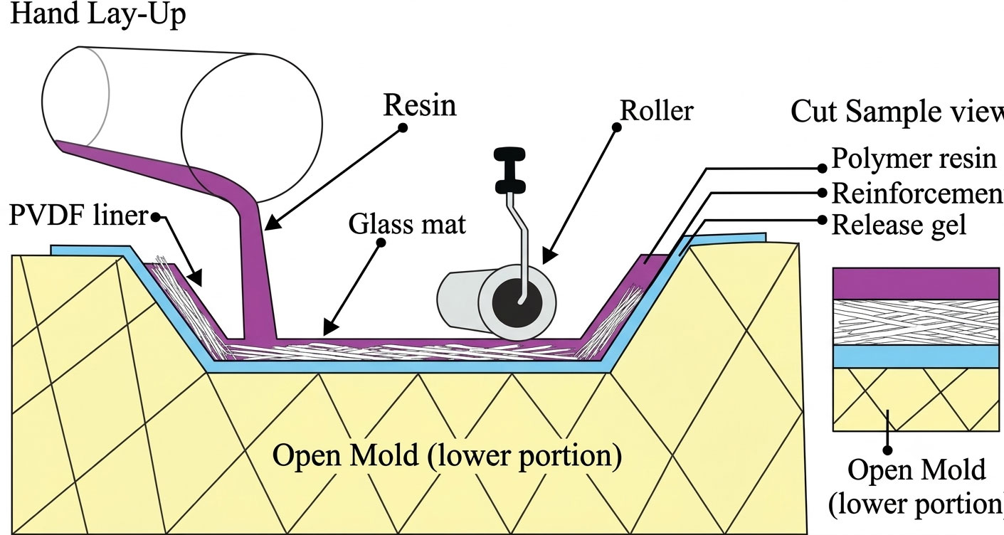
- Materials — the resin and liner chosen for the liquor, temperature and any oxidisers present.
Where sizing usually goes wrong
In our experience, the failures trace back to the same few mistakes: sizing on normal instead of actual flow, choosing water where the gas needed a reagent, ignoring a secondary contaminant, under-wetting plastic packing, and guessing the pressure drop.
Every one of them is avoidable with a complete gas analysis at the start. If you send us the flow, temperature, every contaminant and its concentration, and your outlet limit, we'll size the tower against them — and show you the calculation.